23 CRM DPW-5 Wing–Body — SA Grid-Convergence Verification
WakeCFD SA Hex, Prism, and Hybrid on the common L1–L4 meshes
23.1 Run Provenance and Artifacts
| Item | Value |
|---|---|
| Wake CFD baseline version | 0.23.0 |
| Solver | DBNS |
| Compute device | CPU cluster |
| Parallel execution | 120 MPI ranks across 4 nodes |
| Arithmetic precision | Not recorded in the source report |
| Run dates | 2026-10-12 |
The published CSV is the SA-only subset of the research run’s cl05_results.csv. It records the interpolated values used in the table and chart below. Results from the earlier run001–003 campaign are excluded because those runs preceded a wall-distance correction.
23.1.1 Downloadable Files
| File | Description | Format |
|---|---|---|
| SA grid-convergence results | All 12 mesh-family/level points plotted below; CD is in drag counts |
CSV |
| DPW-5 participant band | Digitized reference envelope and median plotted behind the Wake CFD results | CSV |
| Chart script | Regenerates the SA-only comparison figure from both CSV files | Python |
The complete input decks and solver field files are not published here. Some original 0.17.2 run files were lost; the affected values survive in the research results CSV and cannot be rechecked against their run histories.
23.2 Verification Objective
Assess whether the computed lift-matched drag, angle of attack, and pitching moment approach consistent values as the common DPW-5 CRM wing–body meshes are refined from L1 to L4. The comparison uses the workshop’s code-to-code results. The wind-tunnel model includes deformation and support effects absent from this rigid, free-air CFD geometry, so this case does not claim direct experimental validation.
23.3 Reference Solution and Data
The reference is the AIAA Fifth Drag Prediction Workshop (DPW-5) Common Grid Study for the NASA Common Research Model wing–body configuration. The grey envelope and dotted median in the figure were digitized from the participant curves in the workshop summary figure; extreme outliers were excluded with a 3 × IQR rule in the research dataset. The envelope includes multiple codes and modeling choices, so it is context for the Wake CFD refinement trend rather than a unique exact solution or an SA-only target value. The grey band’s irregular edges reflect the digitized participant curves and should not be interpreted as a continuous physical uncertainty bound.
23.4 Simulation Conditions
| Item | Setting |
|---|---|
| Geometry | CRM wing–body half model, without horizontal tail |
| Flow | Steady, fully turbulent, compressible RANS |
| Freestream | Mach 0.85, Reynolds number 5 × 10⁶ based on reference chord, static temperature 310.928 K |
| Target lift | CL = 0.500; interpolated from separate α = 2.25° and 2.70° runs at each mesh level |
| Drag unit | 1 count = 0.0001 in CD |
23.5 Mesh
DPW-5 common prism, hex, and hybrid mesh families were used with the same node counts at each level. The half-model mesh coordinates were converted from inches to metres.
| Level | Nodes |
|---|---|
| L1 | 660,177 |
| L2 | 2,204,089 |
| L3 | 5,196,193 |
| L4 | 17,441,905 |
23.6 Boundary and Initial Conditions
The half model uses a symmetry plane, no-slip adiabatic walls, and a farfield boundary. The SA freestream working variable is initialized at ν̃/ν = 3. The hybrid L4 α = 2.70° run required a warm start from its 2.25° solution; the other initial fields are not documented individually in this report.
23.7 Numerical Methods
| Item | Setting |
|---|---|
| Turbulence | SA-neg, with ft2, QCR, and rotation correction off |
| Convective flux / reconstruction | Roe / second-order U-MUSCL, κ = 0.5, no limiter |
| Time marching | Backward-Euler implicit, adaptive CFL |
| Gradient settings | Prism: WLS physical / least-squares reconstruction; hybrid: Green–Gauss / Green–Gauss; hex: Green–Gauss / least-squares at L1–L3, Green–Gauss / Green–Gauss at L4 |
| Hex L4 SA adjustment | Turbulence cfl_reduction = 0.25 instead of 0.7, after the original setting diverged |
| Stop rule | Lift/drag monitor window or the 5,000-iteration limit; several runs reached the limit with forces nearly stationary |
α and CMy at CL = 0.5 are linearly interpolated between the two angle-of-attack runs. CD is evaluated from a two-point fit of CD = a + b CL². These are postprocessed values, not separate fixed-lift solver runs.
23.8 Results
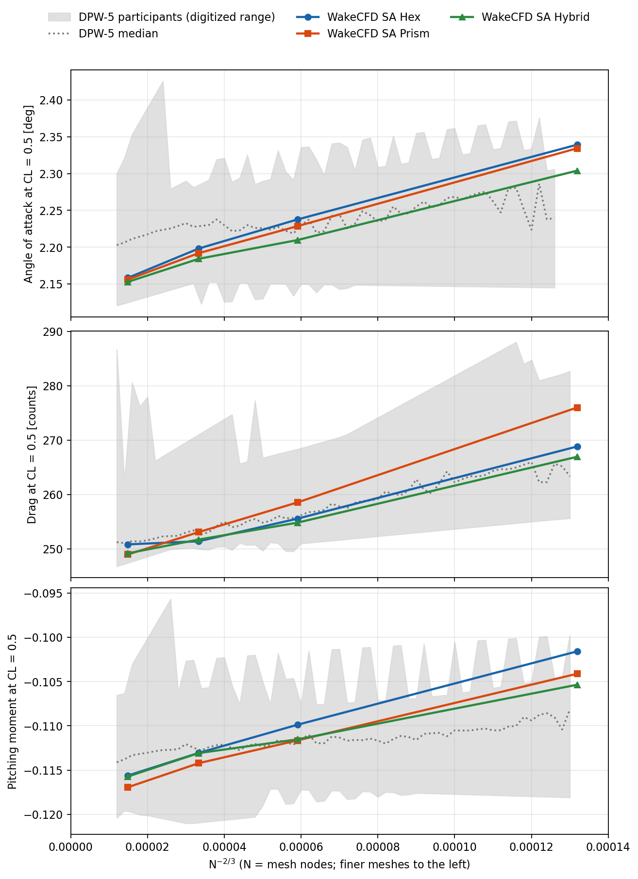
| Mesh | Level | α at CL=0.5 [°] | CD [counts] | CMy |
|---|---|---|---|---|
| WakeCFD SA Hex | L1 | 2.3393 | 268.8 | −0.1016 |
| WakeCFD SA Hex | L2 | 2.2376 | 255.6 | −0.1099 |
| WakeCFD SA Hex | L3 | 2.1981 | 251.4 | −0.1131 |
| WakeCFD SA Hex | L4 | 2.1582 | 250.8 | −0.1156 |
| WakeCFD SA Prism | L1 | 2.3344 | 276.0 | −0.1041 |
| WakeCFD SA Prism | L2 | 2.2285 | 258.6 | −0.1117 |
| WakeCFD SA Prism | L3 | 2.1918 | 253.1 | −0.1142 |
| WakeCFD SA Prism | L4 | 2.1559 | 249.0 | −0.1169 |
| WakeCFD SA Hybrid | L1 | 2.3040 | 267.0 | −0.1054 |
| WakeCFD SA Hybrid | L2 | 2.2096 | 254.8 | −0.1115 |
| WakeCFD SA Hybrid | L3 | 2.1841 | 251.7 | −0.1131 |
| WakeCFD SA Hybrid | L4 | 2.1527 | 249.2 | −0.1157 |
At L4 the three families give α = 2.1527–2.1582° and CD = 249.0–250.8 counts. Their drag spread decreases from 9.1 counts at L1 to 1.9 counts at L4. These L4 values fall within the DPW-5 participant range summarized in the research campaign, but that range combines different methods and turbulence models.
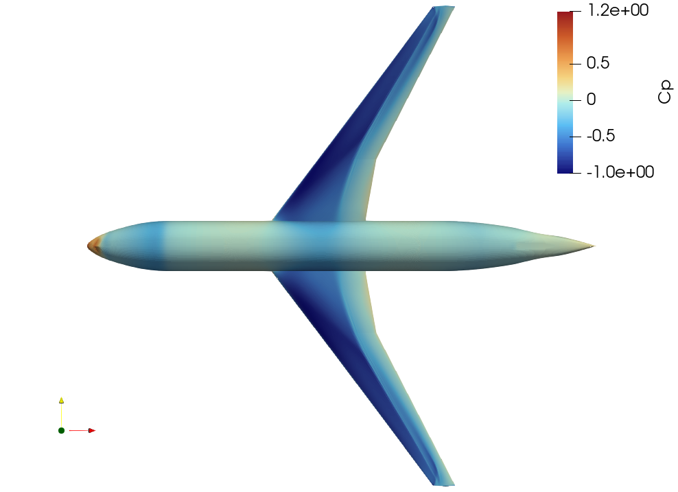
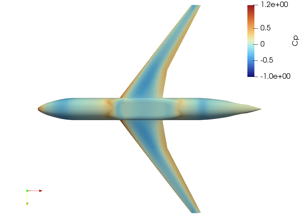
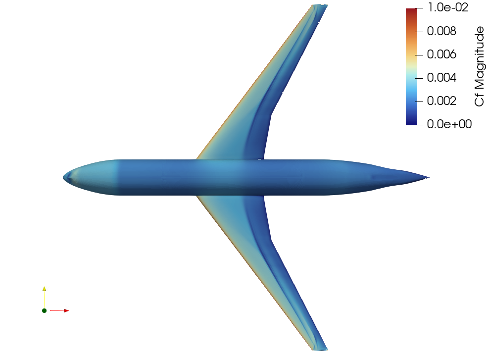
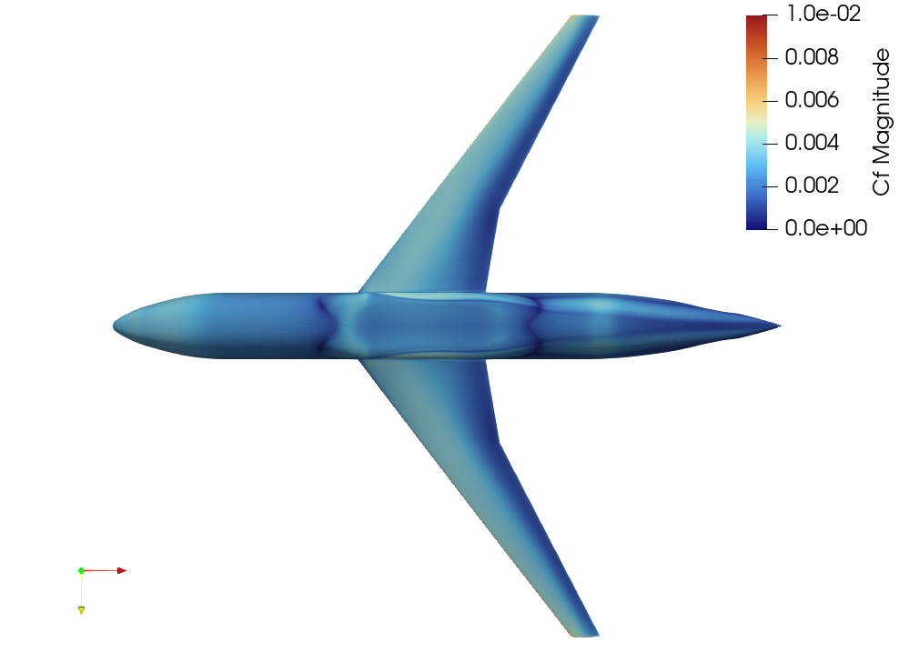
23.8.1 Surface contours: hex L3 SA
The following four images show upper and lower surface pressure coefficient (Cp) and skin-friction magnitude (Cf) from the research campaign’s hex L3 SA result. The original images identify the mesh and turbulence model, but do not identify the exact angle of attack or solver binary; their association with a specific run could not be verified from the retained field files. They illustrate the surface patterns and are not a quantitative comparison with a CL = 0.5 result or with experiment. The displayed scales are Cp = −1.0…1.2 and Cf = 0…0.01.
23.9 Conclusions and Applicable Scope
The SA results show a consistent reduction in drag and angle of attack with refinement across three mesh families, with close agreement between families at L4. This is evidence for this specific CRM wing–body setup and numerical configuration; no formal Richardson extrapolation or discretization-error bound is claimed here.
Interpret the hex curve with care: its L4 reconstruction differs from L1–L3. The runs also mix 0.17.2 and 0.19.0 binaries, and a separate repeat of hybrid L1 on those builds differed by 6.4 drag counts for a reason not yet established. The available data therefore do not isolate mesh refinement from every other numerical change. This case does not establish accuracy for SST, buffet onset, other Mach or Reynolds numbers, or different near-wall treatments.
23.10 References
- Levy et al., Fifth AIAA CFD Drag Prediction Workshop summary, AIAA 2013-0046.
- Park et al., Fifth AIAA CFD Drag Prediction Workshop CFD results, AIAA 2013-0050.