8 2D Laminar Flat-Plate Boundary Layer — FR Blasius Verification
Verification of the p2 Flux Reconstruction solver against the Blasius velocity profile and skin-friction solution
8.1 Run Provenance and Artifacts
| Item | Value |
|---|---|
| Wake CFD baseline version | 0.22.0 |
| Solver | FR |
| Compute device | GPU (NVIDIA RTX A2000 12GB) |
| Parallel execution | 1 MPI rank |
| Arithmetic precision | FP64 |
| Run date | 2026-09-23 |
Results depend on the solver build that produced them. Read every figure in this report together with the version and date above — re-running the same input on a later build may give different numbers.
8.1.1 Downloadable Files
Not available: standalone input decks and solver result files have not yet been published for download.
8.2 Verification Objective
This case simulates the developing laminar boundary layer over a two-dimensional flat plate with the Flux Reconstruction (FR) solver. The final numerical solution is compared with the Blasius similarity solution to verify:
- the no-slip viscous-wall treatment in the FR solver
- third-order
p2solution accuracy on a stretched quadrilateral mesh - collapse of velocity profiles at several streamwise stations in similarity coordinates
- local skin-friction evaluation from FR wall flux points
- dual-time integration of a low-Mach viscous flow
The geometry and freestream condition match the DBNS laminar flat-plate case, so the result also adds an independently implemented solver track to the common flat-plate verification family.
8.3 Reference Solution and Data
8.3.1 Analytical Solution
For a zero-pressure-gradient laminar boundary layer, let x denote distance from the plate leading edge, y the wall-normal distance, U_inf the freestream velocity, and nu the kinematic viscosity. The similarity coordinate and local Reynolds number are
\[ \eta = y\sqrt{\frac{U_\infty}{\nu x}}, \qquad Re_x = \frac{U_\infty x}{\nu}. \]
The Blasius solution gives u/U_inf = f'(eta) and
\[ \delta_{99}\sqrt{\frac{U_\infty}{\nu x}} \approx 4.91, \qquad C_f(x)=\frac{0.664}{\sqrt{Re_x}}. \]
Velocity profiles taken at different x/L stations should therefore collapse onto one curve when plotted against eta.
8.4 Simulation Conditions
| Item | Setting |
|---|---|
| Dimension | 2D |
| Domain | x=[0, 0.762] m, y=[0, 0.1524] m |
| Flat plate | x=[0.1524, 0.4572] m, L=0.3048 m |
| Analysis | Unsteady, compressible laminar Navier–Stokes, evaluated at t=12 s |
| Mach number | 0.1 |
| Reynolds number | Re_L=100,270 |
| Freestream | P_inf=101325 Pa, T_inf=297.62 K, rho_inf=1.1827 kg/m³, U_inf=34.63 m/s |
| Viscosity | Constant, mu=1.245×10^-4 Pa·s |
The viscosity is selected to obtain Re_L≈10^5 at M=0.1; this is a numerical verification condition rather than a specific ambient-air experiment. Although the wall is isothermal, this report does not make a heat-transfer claim because the retained run output does not contain the required integrated heat-flux monitor.
8.5 Mesh
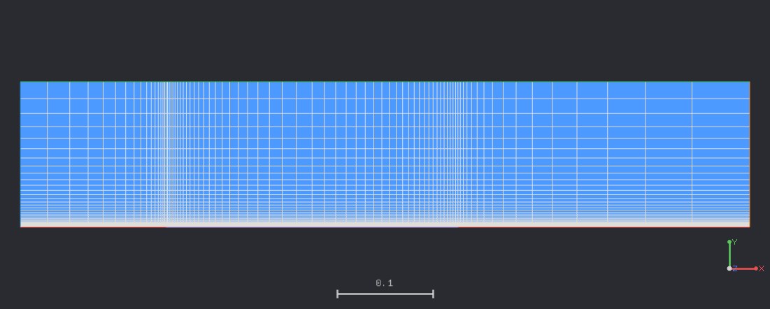
The structured mesh has 80×40=3,200 linear quadrilateral cells. It is clustered at the plate leading and trailing edges and stretched in the wall-normal direction, with a first wall-cell height of 1.5×10^-4 m. With an FR p2 basis, each cell contains nine solution points, giving 28,800 solution points and 144,000 scalar conservative-variable degrees of freedom.
8.6 Boundary and Initial Conditions
| Boundary | Type | Setting |
|---|---|---|
| Left | Farfield inlet | M=0.1, P=101325 Pa, T=297.62 K |
| Right | Pressure outlet | P=101325 Pa |
| Top | Farfield | Freestream condition |
| Bottom outside plate | Free-slip wall | Zero normal velocity |
| Plate | No-slip isothermal wall | T_wall=327.38 K |
Initial field: Not reported.
8.7 Numerical Methods
| Item | Setting |
|---|---|
| Spatial discretization | FR p2 (third order), quadrilateral elements |
| Convective interface flux | Rusanov |
| Viscous interface parameters | LDG beta=0.5, tau=0.3 |
| Physical-time integration | Dual-time BDF1, dt=5×10^-3 s, 2,400 steps |
| Pseudo-time integration | RK45 with local-PI control, CFL=0.3 |
| Inner iterations | 10 minimum, 300 maximum per physical step |
The run advances from a uniform freestream state to t=12 s. Each physical step reached the configured 300-inner-iteration cap, and no inner residual stopping tolerance was enabled. The comparison below therefore assesses the final time-marched solution; it is not evidence of formal pseudo-time or grid convergence.
8.8 Results
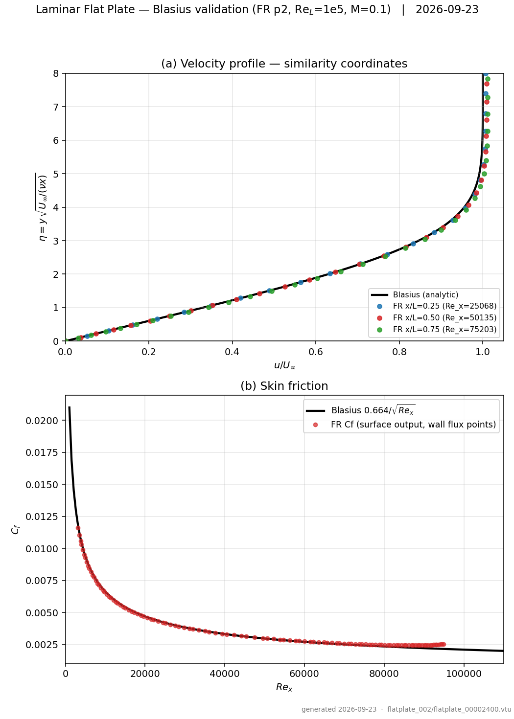
The final velocity profiles at x/L=0.25, 0.50, and 0.75 follow the Blasius curve closely. RMS errors in normalized velocity remain below 1% at all three stations. The boundary-layer thickness is slightly underpredicted, with the largest difference at the downstream station.
x/L |
Re_x |
RMS error in u/U_inf |
Computed delta_99(eta) |
Difference from 4.91 |
|---|---|---|---|---|
| 0.25 | 25,068 | 0.53% | 4.673 | -4.8% |
| 0.50 | 50,135 | 0.66% | 4.621 | -5.9% |
| 0.75 | 75,203 | 0.97% | 4.517 | -8.0% |
Over 0.2≤x/L≤0.9, the median absolute deviation of local Cf from the Blasius solution is 2.0%; the worst sampled deviation is 10.8%. The median signed ratio is Cf_FR/Cf_Blasius=1.021, indicating a small overall overprediction of wall shear in the evaluated interval.
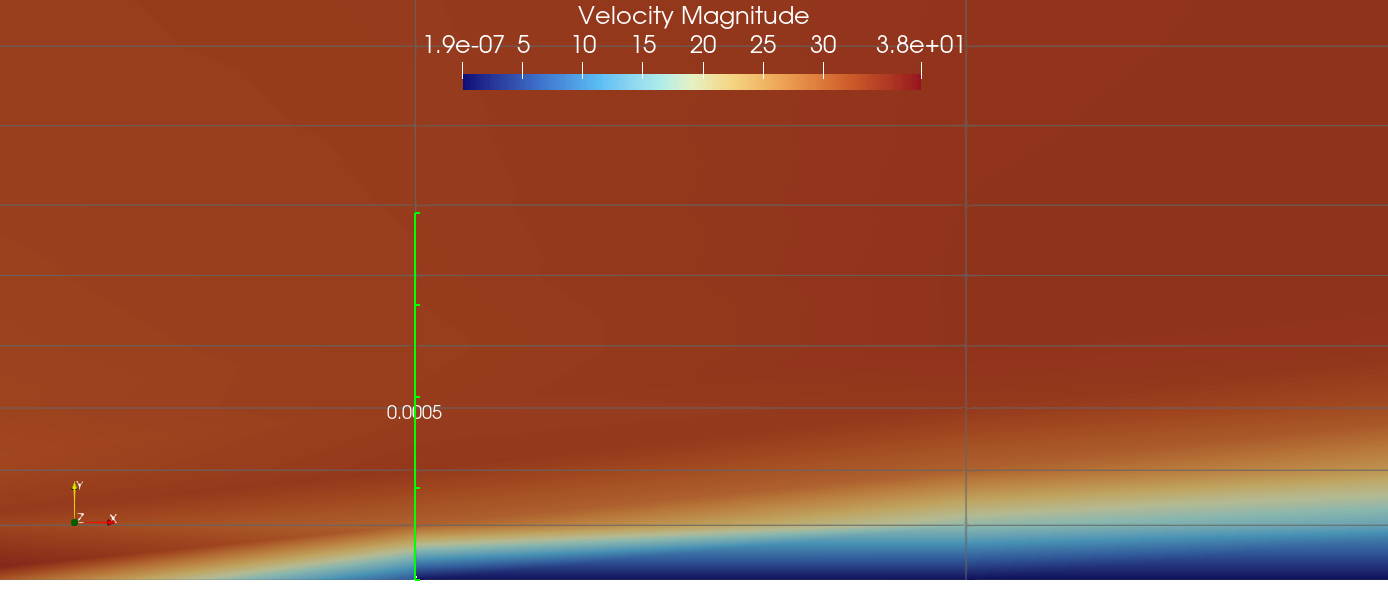
The velocity contour shows the boundary layer growing downstream from the plate leading edge. The plotted region is limited to the near-wall field so that the thin low-speed layer remains visible.
8.9 Conclusions and Applicable Scope
- The FR
p2solution reproduces the Blasius normalized velocity profiles with less than 1% RMS error at all three sampled stations. - Local skin friction agrees with the analytical solution to a 2.0% median absolute deviation over
0.2≤x/L≤0.9; the largest sampled deviation is 10.8%. - The boundary-layer thickness is underpredicted by 4.8–8.0%, with the discrepancy increasing downstream.
- This result verifies the combined FR viscous-wall, wall-flux, and dual-time path for one
p2mesh atM=0.1andRe_L≈10^5. - The run does not establish mesh, polynomial-order, time-step, or pseudo-time convergence. Those variables should be varied independently before broader accuracy claims are made.
- No Pohlhausen heat-transfer result is reported because the retained history file lacks the integrated heat-flux quantities required for that comparison.
This case establishes a baseline for laminar flat-plate calculations with the FR solver. It does not cover turbulent flow, pressure gradients, separation, transition, curved walls, or other Reynolds and Mach numbers.
8.10 References
- Blasius, H., “Grenzschichten in Flüssigkeiten mit kleiner Reibung,” Zeitschrift für Mathematik und Physik, 56, 1908, pp. 1–37.
- White, F. M., Viscous Fluid Flow, 3rd ed., McGraw-Hill, 2006, Chapter 4.